【μBITX とは?】【μBITX 組立て方】【HOME】
本記事は、μBITX 販売元である HF Signals 社を設立された Ashhar Farhan 氏より許諾を受け掲載しているものではありますが、同社、Farhan 氏、並びに私自身も、本ブログに記載の事柄に責任を持つものではなく、すべては皆さんの自己責任にてご判断、ご実施頂きますようお願い申し上げます。
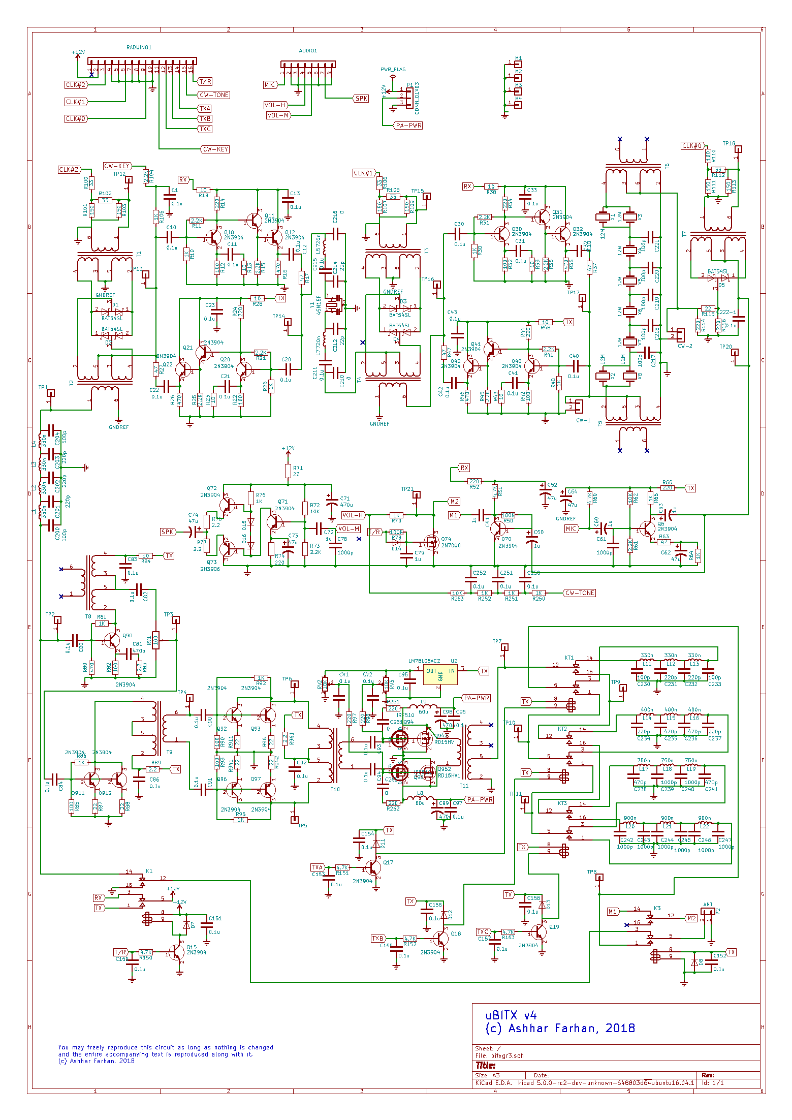
本節では、μBITX のバージョン4(v4、たまに r4 と呼ぶ人もいます)の解説をして参ります。
(注)以前のバージョンは3の情報はコチラをクリックください(英語です)
μBITX v4 の主な特徴は以下のとおりです。
- 低いバンドは約 10W 程度、28 MHz 等高いバンドでは 5W 程度の出力
- SSB と CW をサポート
- 製作、調整が容易
- 最低限の操作パネル
- Arduino Nano をコントローラに、Si5153(DDS – Direct Digital Synthsizer)を発進子として用いた “Raduino” をコアとするハードウェア
- ダブル・コンバージョン スーパーヘテロダイン方式
- 部品代自体は5~6千円程度の汎用品を活用
自作される多くの方々は、マルチバンドのトランシーバ製作は複雑で難しいものとして、かなり抵抗があろうかと思います。しかしながら、CDG2000 トランシーバ(G3SBI, Colin Horrabin 氏、G8KBB, Dave Roberts 氏、G3OGQ, George Fare 氏によりデザインされた。参考URL)の登場で、皆の意識が大きく変わりました。SDR(Software Defined Radio)という考え方が、様々な設計の簡略化を促進し、デジタル信号処理のコストを大幅に削減しました。
一方で、多くの自作を志す方々は、日常使いできる HF トランシーバや、検証/調整のためのワイドバンドなトランシーバを必要としています。結局のところ、多くの方々がこういった用途のために、昔からある FT-817ND といった無線機を購入されているのではいでしょうか。
μBITX を開発する前には、”Minima” というパフォーマンスに優れたマルチバンド・トランシーバ を開発しました。Minima の KISS(Keep It Simple & Stupid – バカバカしいほどシンプルにした)ミキサーは、受信部において非常に良くできたフロントエンドでしたが、キャリア漏れがあることで、完全なるトランシーバに仕立て上げることは断念せざるを得ませんでした。
その後何箇月にも渡り、多くの自作家が最終的に行きつくであろうワイドバンド HF トランシーバの必要性を強く感じておりました。自作可能な、市場性のあるパフォーマンスを有するマルチバンド・トランシーバの開発は、とても複雑なタスクである一方で、VE7CA による “HBR2000” というトランシーバは、複雑性をとことんまでも排除し、十分に実用に耐えうるデザインであることを証明しておりました。
μBITX は、このような必要性を満たすことを目的に開発され、多少のトレードオフはありますが、コンパクトで、HT 帯をすべてカバーするシングルボードなリグなのです。このリグは、約1年間、VU2EUE により、40m や 20m にて日々の運用に使われてきました。いつものシャックでの交信や、時には野外運用にも持ち出して、十分に満足する結果が得られた次第です。
A key challenge for multiband transceivers has been to realize a local oscillator system with such wide range. Silicon Labs has now produced a series of well-performing oscillators that solve this challenge trivially : You connect the oscillator chip over a pair of I2C lines and it is done. The Si5351a/b/c are one such a family of parts that provides 3 programmable oscillator outputs in a small 10 pin TSSOP package. We exploit this chip to build the multiband transceiver.
Having exclusively used homebrew transceivers all the time, I get very confused whenever I need to use a commercial radio. There are too many switches, modes and knobs to twirl around. The µBITX use an Arduino to simplify the front panel while retaining all the functionality in a simple menu system that works with the tuning knob and a single function button. The rig supports two VFOs, RIT, calibration, CW semi break-in, meter indicator, etc. In future, more software can be added to implement keyer, SWR display, etc.
The Circuit Description
A contemporary approach to multiband superhet radio is to upconvert the entire spectrum of interest (0.5 to 30 Mhz) to much higher intermediate frequency that is at least 1-½ times the highest frequency of interest (for us that would be 45 MHz). Though narrow band SSB filters are available at 45 MHz, they are do not have a good response in addition to being costly and difficult to obtain. Hence, we choose to an inexpensive, though 15 KHz wide, 2 pole 45 MHz filter as a roofing filter. This filter sets the wide-range IMD of the receiver.
To tune from 0 to 30 MHz, the first oscillator tunes from 45 MHz to 75 Mhz. Accordingly, the IF images will be from 90 MHz to 125 MHz. These are easily stripped away by a 4-section, low pass filter in the front-end. A higher first Intermediate Frequency could have resulted in even better image rejection.
The second IF of 12 MHz allows for a very reasonable SSB bandwidth filter. We use 8 well-matched low cost crystals to obtain a very smooth filter. Some CW operators may also want to add a second narrow band filter for CW work, more on this when we discuss the CW mode.
Here is the block diagram of the µBITX :

Low Pass filter at 30 MHz

The receiver front-end has a 0-30 MHz filter low pass filter (shown as the left-most block in the diagram above). This is a simple four-section filter that was interestingly described by Wes Hayward on his own website, (the original article that had very useful information about building filters on pcbs. It is, sadly, no longer available). The four sections of low pass filtering has adequate attenuation at 90 MHz and beyond.
1st Conversion

The receiver front-end has a doubly-balanced diode mixer without a preamplifier. A preamp would have been necessary if the front-end had a higher loss band pass filters. The low pass filter has a loss of about 1 db, eliminating the need for a preamp to follow it. The diode mixer’s loss is another 7 db. The overall noise figure is probably about 13db. A 0.1uv signal is clearly audible.
The diode mixer is a standard issue doubly-balanced mixer. Versions built with 1N4148 as well as BAT54S (a very inexpensive, useful part that has two matched diodes in a single SMD package) work equally well.
The [CW_KEY] label in the above circuit provides CW operation. We will discuss this later in this article.
You should know about the front-end mixer :
- A preamp would have been necessary if the front-end had a higher loss band pass filters.
- The low pass filter has a loss of about 1 db, eliminating the need for a preamp to follow it.
- The diode mixer is a standard issue doubly balanced mixer. Version built with 1N4148 as well as BAT54S.
- (a very inexpensive, useful part that has two matched diodes in a single SMD package) work equally well. The diode mixer has a DC bias that can be raised to unbalance it and allow CW operation (more about it later)
- The mixer is fed from clock#2 of the Si5351 through an attenuation pad. The pad provides proper termination to the Si5351 and a proper drive to the diode mixers.
The diode mixers need an SWR of 1:1 at all the three ports (RF, IF and the oscillator drive). Improper matching of the diode mixers can lead to a large number of spurious responses.
For those building the µBITX from scratch, remember that the leads from the Si5351 to this mixer should be kept very short. Longer leads will result in picking up of clock #1 signals from the Si5351 which can create transmit spurs that are 12 Mhz away from the carrier frequency.
The mixer is followed by a post-mixer amplifier (labelled RX 1st AMP). We used the excellent termination insensitive amplifiers (TIA) developed by Wes Hayward and Bob Kopski (read about them on www.w7zoi.net). These amplifiers work without transformers and they provide excellent termination on both sides. This is a key requirement for bidirectional transceivers like the µBITX . We use four blocks of these amplifiers in this transceiver. The amplifier block has a gain of 16 db and OIP3 of about +20 dbm as measured inside the µBITX .
This amplifier does three important things at once :
- it provides necessary gain to overcome the losses in the following 45 MHz band pass filter,
- it provides proper broadband termination to the mixer at all HF frequencies,
- it provides proper driving impedance for the 45 MHz band pass filter.
45 MHz Band Pass Filter
A low cost two-pole 45 MHz crystal filters are now widely available from online sources. We used this to eliminate the guess work with tuning a band pass filter and also to provide better selectivity early in the transceiver’s signal path.
The 45 MHz filter needs 500 ohms termination impedance on both ports. We use simple L network to match the filter to either ends of the front-end and the 2nd IF mixer.
Note: We had use a series tuned, three section band pass filter at 45 MHz for the prototype. This filter was been purposefully kept a little broad to eliminate the need to tune it. Experimentally inclined scratch-builders may choose to use air core coils with proper shielding for this stage.
2nd Conversion
The second RF mixer down converts the 45 MHz IF to 12 MHz. It is another standard issue double-balanced diode mixer followed by another clone of the RF amplifier used in the front-end. To invert the sideband between USB and LSB, the second oscillator is switched between 33 MHz and 57 MHz. This is controlled by the µBITX software.
12 MHz SSB filter

The ladder topology is now enhanced with the improvisation suggested by G3UUR. Paralleling up crystals at two ends of the regular ladder filter of Cohn topology really flattens out the response and even improves the losses. We use a six-section ladder filter here as we can afford the slightly higher losses given that we have had enough gain from the preceding stages.
Microprocessor-grade crystals are available cheaply and are well suited for the purpose. The lower Q of these crystals results in higher losses. We can handle the higher losses by increasing the gain in the 2nd RF amps that in turn results in slightly lower IIP3 (it is about +5 dbm as measured) at close range.
The 12 MHz filter needs 200 ohms termination at both ends. We achieve this through 1:4 transformers that have the robust 50 ohms terminations. Taking care to terminate filters properly is the secret to having a nice sounding radio.
(De)Modulator
The post filter signal is strong enough to not need an IF amplifier, so we directly take it to a balanced (de)modulator made out of two matched diodes. It is important to use matched diodes here as the same circuit is also used to modulate during transmission.
Balance controls are pesky circuits, they are easily unbalanced and setting them properly is more difficult than finding two diodes with the same forward resistance and soldering in the pair. An easier option it to just order a small strip of the inexpensive BAT54S which come as pre-matched pair for a few pennies each.
We use the remaining CLK#0 output of the Si5351 to drive the BFO. The carrier is permanently fixed to generate upper sideband signal. The sideband is inverted by flipping the second oscillator between 33 MHz and 57 MHz. When the second oscillator is at 33 MHz, the upper sideband propagates either way without inversion as 33 + 12 = 45 MHz. When the second oscillator is at 57 MHz, the 45 MHz is generated as 57-12 = 45 MHz. Note that in the second case, the 45 MHz signal will decrease in frequency as the 12 MHz signal is subtracted from 57 MHz, thus achieving sideband inversion. A few minutes of pencil and paper work will be required to figure out how this works.
Audio

The audio preamp is a carry over from the microR1 direct conversion receiver’s simple audio amp. This must be the simplest circuit block in the radio, yet it has the most gain in the entire receiver chain. Using fewer active devices in the amplifier chain is really the key to low distortion audio. This is supported by Math.
The audio amplifier in the updated (revision 4) uses a low distortion audio amplifier made from discrete transistors. The audio amplifier though meant for pleasing output to a headset. It can drive a small speaker too. You may, if required, substitute this for any other audio amplifier of your choice.
A 2N7000 is used to mute the audio from the signal path while transmitting. It prevents thump of the T/R circuitry from getting into the speaker output.
CW sidetone
The CW sidetone is generated as a square wave from the Arduino. It passes through an RC low pass filter to the audio amp during key down periods
Transmitting
The transmission is really the same signal flow in the reverse direction. The mic has a bias resistor to allow for electret microphones. The output at the low pass filter is about -10dbm. The transmit power chain has a two 2N3904 broad band class A amps that boost the power to about +13 dbm level.

The power chain uses four common plastic 2N3904s in push-pull as drivers. The 2N3904s have enough gain at 30 MHz. The 2N2219s tried earlier were found to have low gain at higher frequencies.
Two IRF510s are used in push-pulll. The IRF510s are a favorite among the homebrewers and they are low cost – an important consideration if you accidentally blow them up.
The push-pull amps cancel the even order harmonics significantly. Four harmonic filters are sufficient to provide more than 43 db of required suppression of spurious outputs.
Software Description
The Arduino source code for the µBITX is available on https://github.com/afarhan/ubitx4
The Arduino works with a common 16×2 LCD display and an Si5351A. The software controls the oscillator, implements two VFOs, and provides a calibration routine. The code is always changing so it may do things not mentioned here.
It is easier to understand the what the software does by watching a video about it
Operating the Radio
The radio is tuned by an encoder. It tunes in steps of 100 Hz. Quicker tuning results in a higher step rate. To change the band you can just flick the tuning knob fast enough!
RIT, sideband change, VFO selection and other options are available through a menu. Pressing down on the tuning encoder’s switch displays the menus. The tuning encoder scrolls through the menu options. The last menu item is an exit option back to regular tuning.
The radio switches automatically to LSB when operating below 10 MHz.
To operate CW, you just grab the key and pound it, there is no mode switch. A single analog line is used to implement the straight key as well as the keyer. The setup menu allows you to chose between Iambic A, Iambic B and a straight (hand) key.
To connect a keyer, connect the dot and dash paddles through a 2.2K and 10K resistors respectively. Internally, the CW key line is monitored to measure the voltage drop across it. A straight key pulls the voltage down to 0v, a dash is 2.5v, etc. The software automatically detects these voltages.
CW Mode
With the fading sunspots, many of our radio compadres are rediscovering the joys of primitive CW where a good ear, a modest dipole and 10 watts still gets you decent DX. The µBITX center stages the CW operation. A personal preference to use wider bandwidth has resulted in a single filter for SSB as well as CW, there is no reason why a line from Arduino cannot be used to switch to a narrower 500 Hz filter for CW.
Given that the BFO is completely progammable, there is little need for the CW filter to also be at 12 MHz, For instance a 5 MHz IF maybe more suitable for a narrow CW filter.
The CW is generated like this:
- The second oscillator and the BFO as disabled
- The first oscillator is moved to the actual transmit frequency
- A DC bias is fed to the first mixer to upset the balance and allow the first oscillator to leak to the RF power chain.
- The CW sidetone is generated from the Arduino and injected into the audio amplifier

Design Notes
Though a double conversion superhet, this design is scarcely more elaborate than its forerunner, the original BITX20. The original BITX20 had three stages of amplification, this has just two. The original BITX20 used two oscillators, this design uses a single Si5351A (the size of a transistor) to generate three frequencies. Technology has dramatically evolved in the last decade. Newer devices, newer platforms, like the Arduino, have put a lot of power and flexibility in the hands of the homebrewer. This design is a testimony to that.
Double conversion radios are considered a complex beast. However, with judicious choice of frequencies and careful distribution of gain, it is possible to get quite satisfactory performance that is just a few decibels below that of a narrow band single conversion superhet. Extensive amount of mental homebrewing with cascade.exe supplied on the EMRFD’s accompanying CD resulted in the current topology. A surprise discovery was that it was wholly unnecessary to add IF amplification after the SSB filter!
The filters were extensively simulated on the software that accompanies the book Experimental Methods in RF Design. The LADBUILD was used to build the filters and the GPLA was used to run the simulations. The transmit filters were simulated on LTSpice. A homebrew spectrum analyzer and and sweeper were used to ascertain the fitlers’ performance.
Two versions of this radio have been built. Both are of exactly the same configuration and they worked smoothly without a hitch.
The entire transceiver, minus the digital board containing the Arduino, Si5351 and the display, was built on a small 6″ by 6″ copper clad, double sided board. Small squares were cut to mount the SMD 1206 size components across them. Except for the Audio power amp, the large value electrolytics and the transmit power chain, SMDs were used everywhere.
The main board has an 8 pin connector that brings volume, mic and speaker wires to the front-panel.
The digital board, also known as Raduino, is a general purpose Arduino board with the Si5351a and the 16×2 LCD display. It has a bottom connector that brings out the three clocks and a few digital pins. This connector mounts on the 6″ by 6″ board with an 16 pin, L-shaped connector.
Another 6 pin connector on the Raduino board brings six analog lines and 5 volts power to the front-panel. This is interfaced to the tuning pot, function button, PTT and the morse key.
There are several places where the layout is critical:
- The bandpass filter and the low pass filter are kept at right angles to each other to reduce coupling
- The Si5351a clocks should have very short leads going to their respective mixers and they should be away each other as well as from any power leads to prevent leakage of their RF into the transmit path.
- The transmit low pass filters are mount as way from the low pass filters as possible.
One could relax these constraints if one used better shielding.
Coil Details
- L5, L7 : 12 turns on T30-6
- L1, L2, L3, L4, L11, L12, L13 : 9 turns on T30-6
- L14, L15, L16: 10 turns on T30-6
- L14, L15, L16: 14 turns on T30-6
- L20, L21, L22: 19 turns on T30-6
All the RF transfomers are 8-10 trifilar turns on FT37-43
Improvements
- Harmonic Filters
- Broadcast filter If there are powerful Medium wave or LF transmitters in the immediate vicinity of your QTH, it will make sense to add a high pass filter with a cut-off around 1.6 MHz to keep these out of the front-end.
- Keyer The keyer line is an analog line with a 10K drop resistor fro 5 volts. Adding a 10K and a 4.7K resistor in series with the left and right paddle will allow us to sense dot and dash as different voltages on the analog pins. A keyer could easily be written after refactoring the present messy CW code.
- Better IF system An IF derived AGC with sufficient gain control, a selection of another narrow band filter can easily add a lot of street cred to this little radio. The hybrid cascode amplifier described by Hayward and Damm is highly recommended.
- VHF/UHF coverage With the 45 MHz IF, it is trivial to build band-pass filters with microstriplines for 144 MHz, 220 MHz and 432 Mhz frequencies. The Si5351’s clock may not high enough for the first conversion directly at 432 Mhz but a sub-harmonic mixer that works with only half the local oscillator frequency can easily scale this rig for VHF/UHF work. MMICs like the MAR6 series and power modules from Mitsubishi can easily scale this radio to reasonable performance level for weak signal and satellite work.
After thoughts
As a fresh radio amateur in the 80s, one looked at the complex multiband radios of the day with awe. I remember seeing the Atlas 210x, the Icom 720 and Signal One radios in various friends’ shacks. It was entirely out of one’s realm to imagine building such a general coverage transceiver in the home lab.
Devices are now available readily across the globe through online stores, manufacturers are more forthcoming with their data. Most importantly, online communties like the EMRFD’s Yahoo group, the QRP LABS and BITX20’s groups.io community etc have placed the tribal knowledge within the grasp of far flung builders like I.
One knows that it was just a matter of breaking down everything into amplifiers, filters, mixers and oscillators, but that is just theory. The practice of bringing a radio to life is a perpetual ambition. The first signal that the sputters through ether, past your mess of wires into your ears and the first signal that leaps out into the space from your hand is stuff of subliminal beauty that is the rare preserve of the homebrewer alone.
At a recent eyeball meet, our friend Dev(VU2DEV) the famous homebrewer said “Now is the best time to be a homebrewer”. I couldn’t disagree.
